Physics - Current Electricity Question with Solution | TestHub
PhysicsCurrent ElectricityElectrical PowerEasy2 minPYQ_2022
PhysicsEasymultiple choice
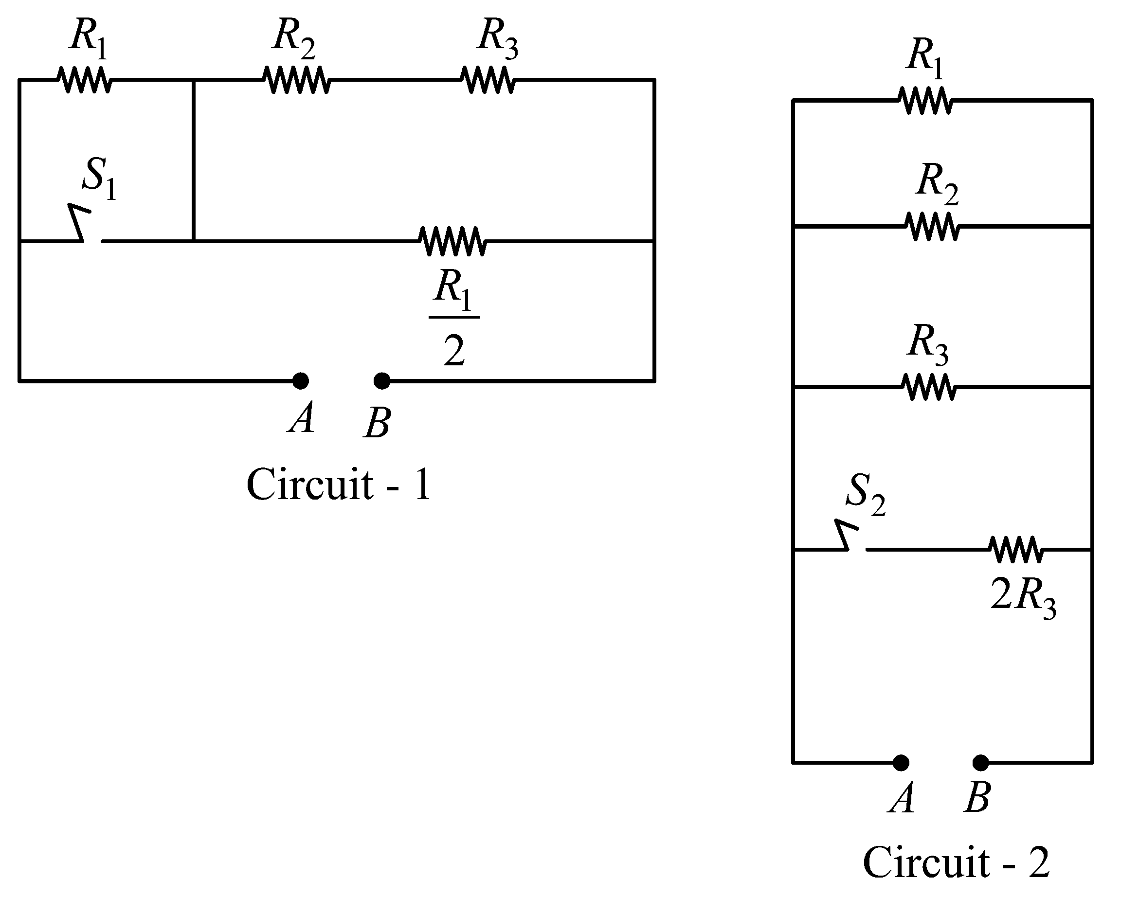
In Circuit- and Circuit- shown in the figures, and .
and are the power dissipations in Circuit- and Circuit- when the switches and are in open conditions, respectively.
and are the power dissipations in Circuit- and Circuit- when the switches and are in closed conditions, respectively.
Which of the following statement(s) is(are) correct?
Options:(select one or more)
Answer:
A, B, C
Solution:
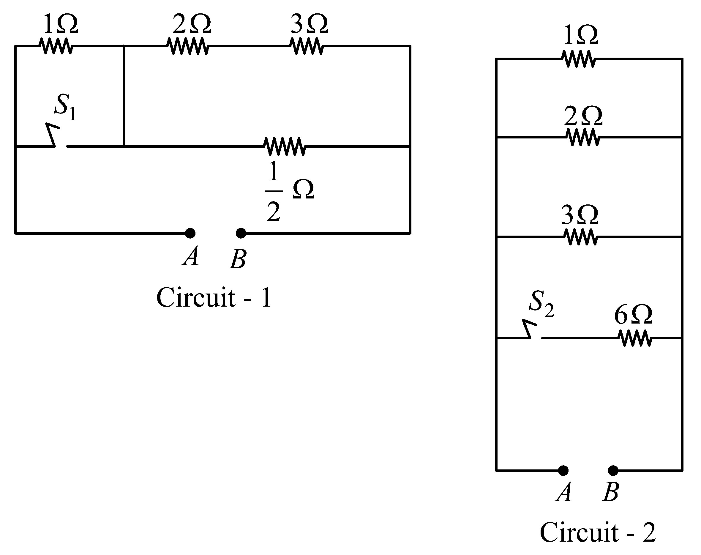
When and are open
For circuit 1
For circuit 2
Therefore,
Option is correct
If A source is used in both cases.
Option is correct.
When and are closed
For
Therefore,
Option is correct.
For option
Option is incorrect.
Stream:JEE_ADVSubject:PhysicsTopic:Current ElectricitySubtopic:Electrical Power
⏱ 2mℹ️ Source: PYQ_2022
Doubts & Discussion
Loading discussions...