
Physics - Semiconductors Question with Solution | TestHub
PhysicsSemiconductorsPN junctionMedium2 minQB
PhysicsMediumsingle choice
A full wave rectifier circuit along with the input and output voltage is shown in the figure. The contribution to output voltage from diode 2 is:
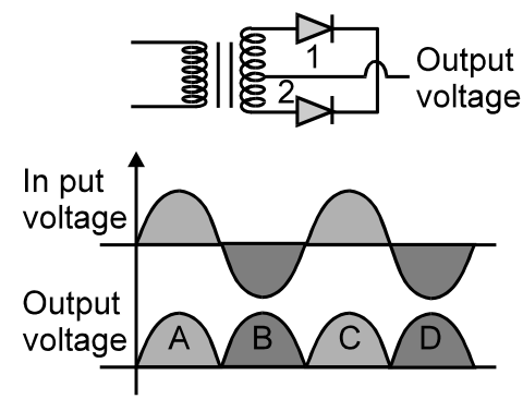
Take the secondary polarity such that diode 1 conducts during the first positive half-cycle of the input.
Options:
Answer:
B
Solution:
In a center-tapped full-wave rectifier, the diodes conduct on alternate half-cycles.
Diode 2 supplies the second and fourth labeled output pulses.
These are B and D.
Stream:JEESubject:PhysicsTopic:SemiconductorsSubtopic:PN junction
⏱ 2mℹ️ Source: QB
Doubts & Discussion
Loading discussions...