
Physics - Semiconductors Question with Solution | TestHub
To obtain the truth-table shown, from the following logic circuit, the gate should be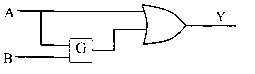
\begin{array}{|l|l|l|}
\hline \mathrm{A} & \mathrm{B} & \mathrm{Y} \\
\hline 0 & 0 & 1 \\
\hline 0 & 1 & 0 \\
\hline 1 & 0 & 1 \\
\hline 1 & 1 & 1 \\
\hline
\end{array}
Options:
Answer:
Solution:

The truth table for given configuration is as shown below.
\begin{array}{|c|c|c|c|c|}
\hline Case & \mathbf{A} & \mathbf{B} & \mathbf{C} & \mathbf{A}+\mathbf{C}=\mathrm{Y} \\
\hline I & 0 & 0 & \mathrm{C}_1 & 0+\mathrm{C}_1=1 \\
\hline II & 0 & 1 & \mathrm{C}_2 & 0+\mathrm{C}_2=0 \\
\hline III & 1 & 0 & \mathrm{C}_3 & 1+\mathrm{C}_3=1 \\
\hline IV & 1 & 1 & \mathrm{C}_4 & 1+\mathrm{C}_4=1 \\
\hline
\end{array}
Considering case (I), in order to have output as has to be 1 . For input values, and , if is to be high, the gate could be either NAND or NOR.
Considering case (II), in order to have output (Y) as has to be 0 . For input values, and . If is to be 0 , the gate must be NOR.